
Dixin Precision Hardware Precision Machining of Hardware Components
-
+86 138 5974 0886
+86 138 5974 0886 Mr. Zhang
+86 186 8533 4928 Miss Zhang -
- language
Dixin Precision Hardware Precision Machining of Hardware Components
+86 138 5974 0886 Mr. Zhang
+86 186 8533 4928 Miss Zhang
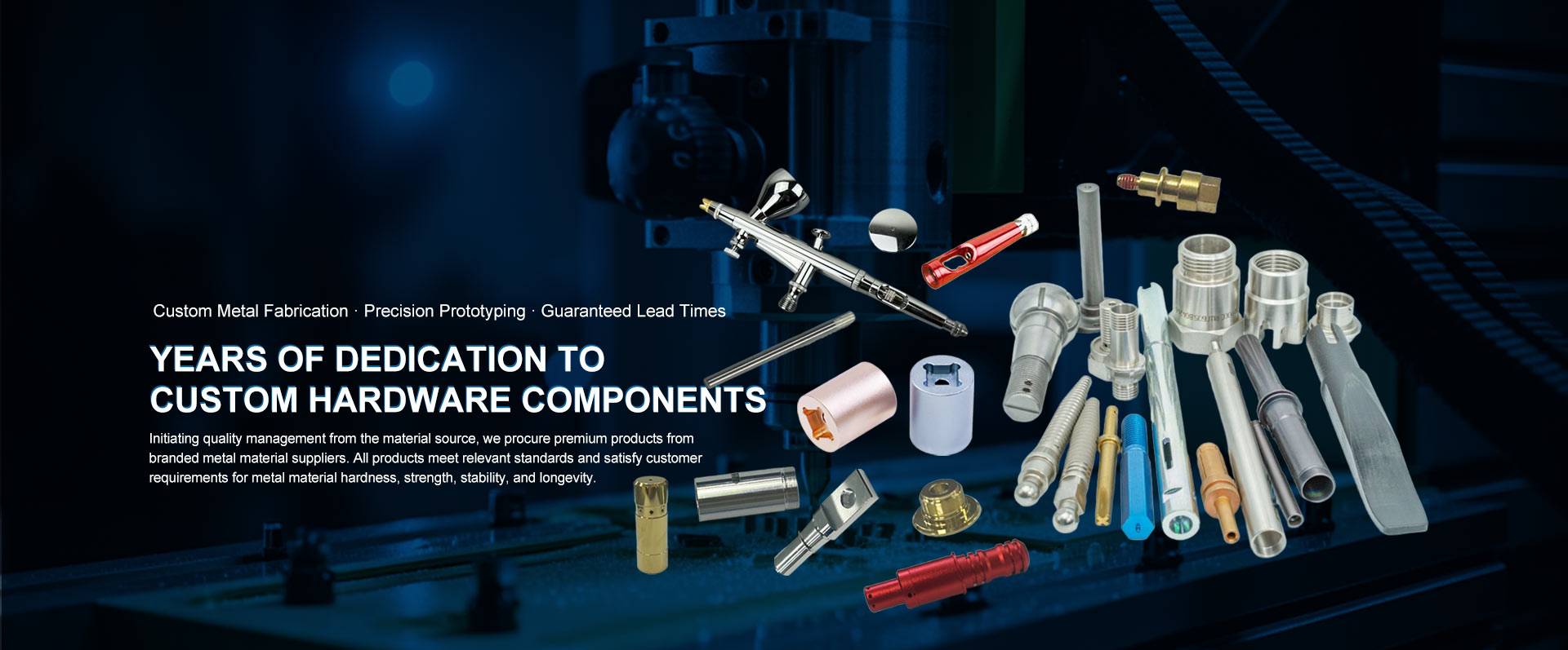
The external cylindrical turning process for lathe-machined parts involves rotating the workpiece via the lathe spindle while coordinating axial feed motion of the cutting tool to remove excess material from the workpiece's outer surface. This achieves the desired dimensions and surface finish. The core process comprises three stages: rough turning, semi-finish turning, and finish turning. Technical parameters and tool selection for each stage must strictly align with machining requirements. The specific process flow and key technical points are as follows:
I. Process Flow
Rough Turning Stage
Objective: Rapidly remove the majority of machining allowance to establish a foundation for subsequent operations.
Parameters: Cutting depth 2-5mm, feed rate 0.3-1.2mm/r, cutting speed 80-150m/min (for carbon steel).
Tooling: Pointed-tip tool with small rake angle (γ=5°-10°) and negative flank angle design to enhance cutting strength.
Accuracy: Tolerance IT13-IT11, surface roughness Ra 12.5-50μm.
Semi-Finishing Stage
Objective: Transition operation to reduce remaining stock and improve surface quality.
Parameters: Cutting depth 0.5-1mm, feed rate 0.2-0.5mm/r, cutting speed increased by 10%-20%.
Tooling: Adjust front angle to 10°-15°, tool rake angle 75°-90°, tip radius 0.5-1mm.
Accuracy: Tolerance IT10-IT9, surface roughness Ra 6.3-3.2 μm.
Finishing Stage
Objective: Achieve final dimensional accuracy and surface finish.
Parameters: Cutting depth ≤0.5mm, feed rate ≤0.3mm/r, cutting speed 200-300m/min (carbon steel).
Tooling: 90° offset tool with large rake angle (γ ≥ 15°) and positive cutting edge inclination, tip radius 0.2 mm.
Accuracy: Tolerance IT7-IT6, surface roughness Ra 1.6-0.8 μm; non-ferrous metals can achieve Ra below 0.4 μm.
II. Key Technical Points
Tool Selection and Adjustment
Rough Turning: Prioritize tools with wide chip evacuation grooves to handle continuous chips, offering superior cutting depth tolerance compared to other tool types.
Finish Turning: Employ a finishing edge design (secondary rake angle kr=0°, length bε=1.2-1.5 times feed rate) to reduce surface roughness to Ra2.5-5μm.
Special Materials: For non-ferrous metals like copper and aluminum, use diamond tools with cutting depth <0.15mm, feed rate <0.1mm/rev, and cutting speed ≈300m/min.
Optimized Cutting Parameters
Cutting Speed:
- Carbide tools: up to 200 m/min
- Ceramic tools: 500 m/min
- PCD tools: 900 m/min (for ordinary steel)
Feed Rate:
- Rough turning: Feed rate is several to over ten times the normal value, requiring a finishing edge for efficient machining.
- Finishing turning: Feed rate ≤ 0.5 mm/r, avoiding tool wear that affects dimensional accuracy.
Cutting Depth: During finishing, cutting depth ≤0.5mm to prevent tool wear from affecting dimensional accuracy.
Quality Control Measures
Dimensional Accuracy: Measure using vernier calipers and micrometers; measurement frequency during finishing ≥3 times per batch.
Shape Error: Cylindricity deviation is corrected via tailstock offset. Straightness errors require verification of lathe guideway parallelism.
Surface Quality: Coolant is used to reduce cutting temperature, decreasing thermal deformation by 40%-60%. For non-ferrous metal processing, coolant must possess rust prevention and environmental protection properties.
III. Typical Application Scenarios
Shaft Component Machining
Process Flow: Rough machining → Rough turning of outer diameter → Heat treatment (normalizing/quenching and tempering) → Semi-finish turning of outer diameter → Finish turning of outer diameter → Grinding (for high precision requirements).
Case Study: During machining of a reducer output shaft (material 40Cr), single-end chucking with a center was used during rough turning. Double-center chucking was employed for semi-finish and finish turning to ensure concentricity ≤0.05mm.
Disc-Type Component Machining
Equipment Selection: Short, thick large disc-type components are machined on vertical lathes to prevent centrifugal deformation.
Process Control: Spindle speed during rough turning is lower than during finish turning. When turning end faces, the saddle must be locked to prevent outward bulging or inward concavity.
Precision Machining of Non-Ferrous Metals
Tool Material: Polycrystalline cubic boron nitride (PCD) tools operate at 900 m/min cutting speeds, achieving surface roughness Ra 0.1–0.4 μm.
Process Innovation: Employing heated turning methods (plasma heating, electromagnetic induction heating) reduces material strength and hardness, boosting cutting efficiency by 3–5 times.
Phone
Contact

TOP